Thermal Zone Heat Pump Wiring Diagram
Zone Valve Wiring Manuals Installation Instructions Guide To

Products Si24diteptc1 50v

Md 9230 Raptor 700r 12v Wiring Diagram Wiring Diagram

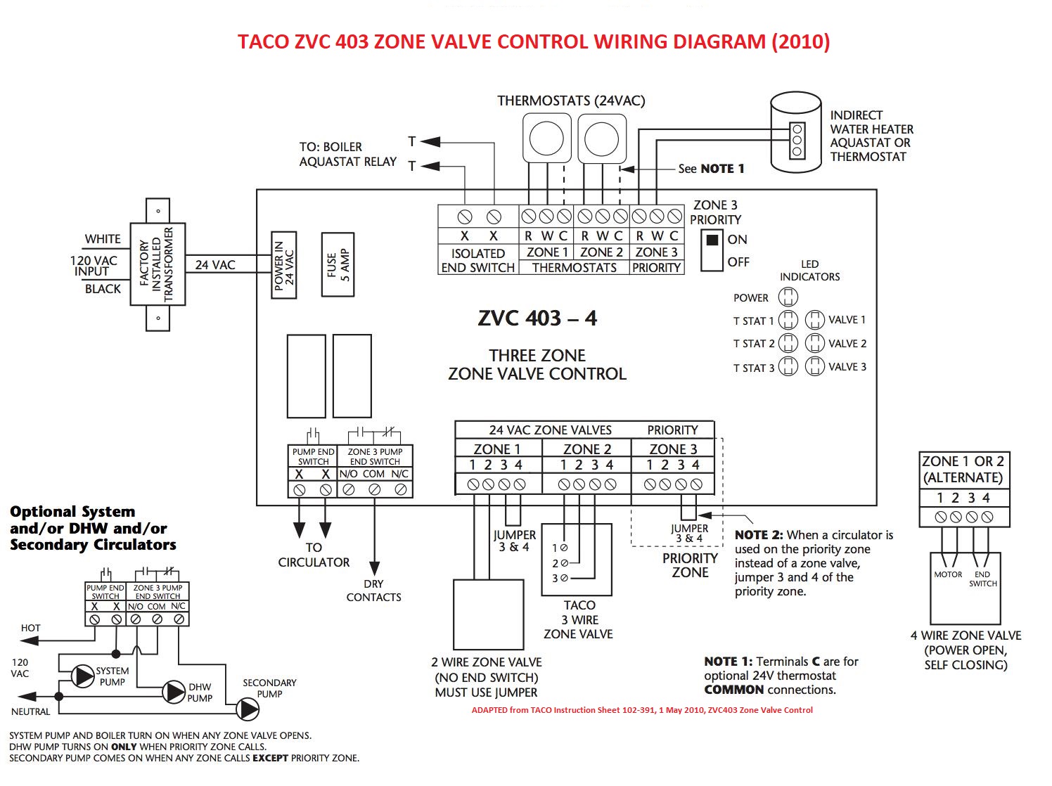
Taco Sentry Zone Valve Wiring Diagram Dengan Gambar

Wiring Geothermal Water Valves Heating And Air Omaha Accurate

3 Zone Heating System Wiring Diagram With Images Central

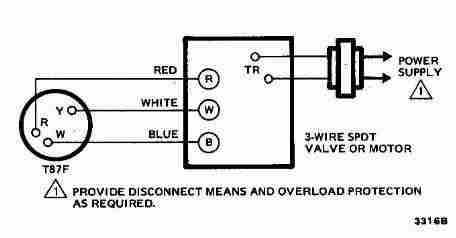
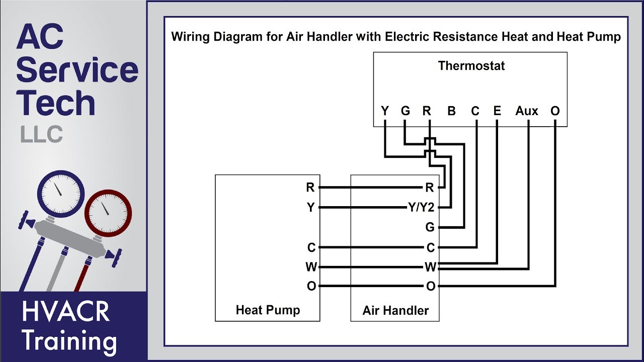
Thermostat wiring diagrams for heat pumps heat pump thermostat wire diagrams.
Thermal zone heat pump wiring diagram. Wiring diagram 1 l 2 n s 9 k a nd 1 2 k 11 5 vac green wire for gnd 115 vac input l1 l2 l1 l2 green wire for gnd l1 l2 l1 l2 24k 230vac green wire for gnd note. Some ac systems will have a blue wire with a pink stripe in place of the yellow or y wire. Do not bundle any excess 24v control wire inside control box. The basic heat pump wiring for a heat pump thermostat is illustrated here.
Electrical shock hazard disconnect power before servicing r connection diagram o bl o bl attach ground ps2 ps1 lp hp lp hp two switch wiring r power supply per n e c. The color of wire r is usually red and c is black. Heat pumps are different than air conditioners because a heat pump uses the process of refrigeration to heat and cool while an air conditioner uses the process of refrigeration to only cool the central air conditioner will usually be paired with a gas furnace an electric furnace or some other method of heating. All fuel kit control wiring heat pump standard thermostat standard furnace outdoor heat pump thermostat.
Ground equipment per n e c. Without auxiliary heat with auxiliary heat 3. Defrost heat compressor heat cool common 24 vac w y bk l1 bk l2 l3 bl t1 comp t3 danger. Heat pump thermostat wiring chart diagram.
It corresponds to the chart below to explain the thermostat terminal functions. This way you have a reference. C is known as the common terminal. Step 12 condensate hose unit is provided with approximately 18 of condensate hose.
And local codes 208 230 vac 60 hz 3 ph. These two connections will ensure that there is power to the thermostat that you are operating. As shown in the diagram you will need to power up the thermostat and the 24v ac power is connected to the r and c terminals. Heat pump user manuals operating guides specifications.
Before uninstalling the old thermostat take a picture of the wiring with your cell phone before removing the wires. Heat pump thermostat wiring a typical wire color and terminal diagram. Install room thermostat on an inside wall that is not subject to drafts direct sunshine or other heat sources. 9 this diagram is to be used as reference for the low voltage control wiring of your heating and ac system.
Page 13 installation cont d.

Https Encrypted Tbn0 Gstatic Com Images Q Tbn 3aand9gctunc3vcqvfxeu5 Ca11jzeb3yo4 Hb2ppluwjx9h7n4zfxj9wi Usqp Cau
Thermal Zone 24h46zomi Manuals Manualslib

Thermal Zone Condenser Install Revisited A Year Later Youtube

York Rooftop Unit Wiring Diagram General Wiring Diagram

Heat Pump Thermostat Wiring Chart Diagram Easy Step By Step

Coleman Rv Air Conditioner Covers Together With Dometic Single
Hvac Control Tutorial Gohts Wiki
Wiring Of A Single Stage Heat Pump Youtube
Pioneer Air Conditioner Ac Mini Split Error Codes And

Heat Pump Wire Diagram Kobe Balmoond19 Mooiravenstein Nl

Honeywell 3 Port Valve Wiring Diagram With Images Central
Thermostat Wiring Diagrams 10 Most Common Youtube