Tempstar Thermostat Wiring Diagram

Need Help With Thermostat Replacement Wiring Doityourself Com
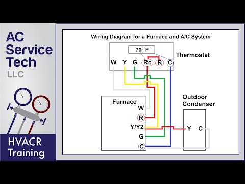
Thermostat Wiring To A Furnace And Ac Unit Color Code How It

Gh 5369 Tempstar Heat Pump Wiring Diagram Additionally Heat Pump
Thermostat Wiring Diagrams 10 Most Common Youtube

Ws 1360 Comfortmaker Heat Pump Wiring Diagram Wiring Diagram
18b9 Tempstar Heat Pump Wiring Diagram Style Ph5542 Wiring Resources
Thermostat wiring and wire color chart thermostat wiring colors code.
Tempstar thermostat wiring diagram. Always follow manufacturers instructions for both the thermostat and the hvac system. Here is a picture gallery about tempstar furnace wiring diagram complete with the description of the image please find the image you need. Yellow wire for cooling. White wire for heat.
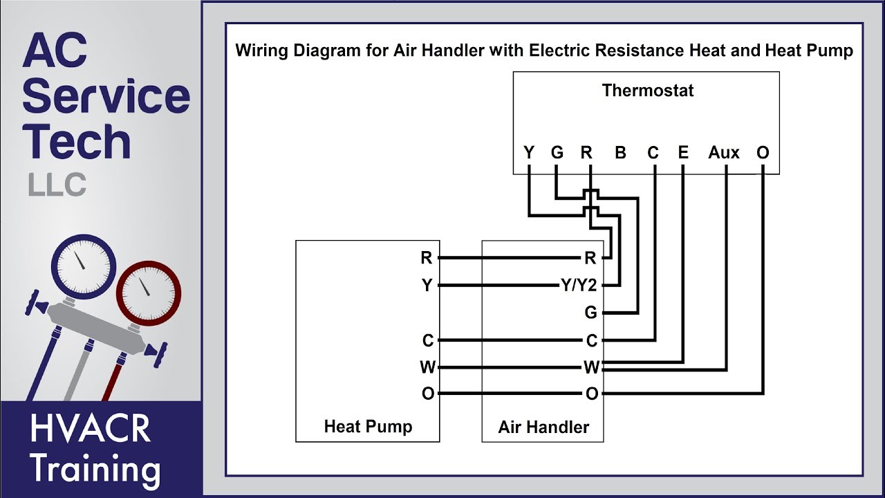
Blue wire is the common wire common wire can be of any other color. Heat pump thermostat wiring chart diagram hvac the following graphics are meant as a guide only. A wiring diagram is a simplified conventional photographic representation of an electric circuit. Red wire for 24 volt hot.
It is a red wire and comes from the transformer usually located in the air handler for split systems but you may find the transformer in the condensing unit. Additional articles on this site concerning thermostats and wiring can help you solve your problem or correctly wire a new thermostat. Tempstar wiring diagram tempstar manuals wiring diagrams with regard to tempstar furnace wiring diagram image size 566 x 300 px and to view image details please click the image. It shows the parts of the circuit as streamlined forms as well as the power and also signal links in between the devices.
Tca924 60gka200 19 seer r 410a wiring diagram tca924 60gka200 19 seer r 410a wiring diagram pdf tca924 60gka200 19 seer r 410a wiring diagram pdf file options. Assortment of tempstar heat pump wiring diagram. It has 5 different color wires each for a different terminal and function. This type of wiring is usually found in air conditioning systems or gas furnaces.

Intertherm Thermostat Wiring Diagram With Images Thermostat
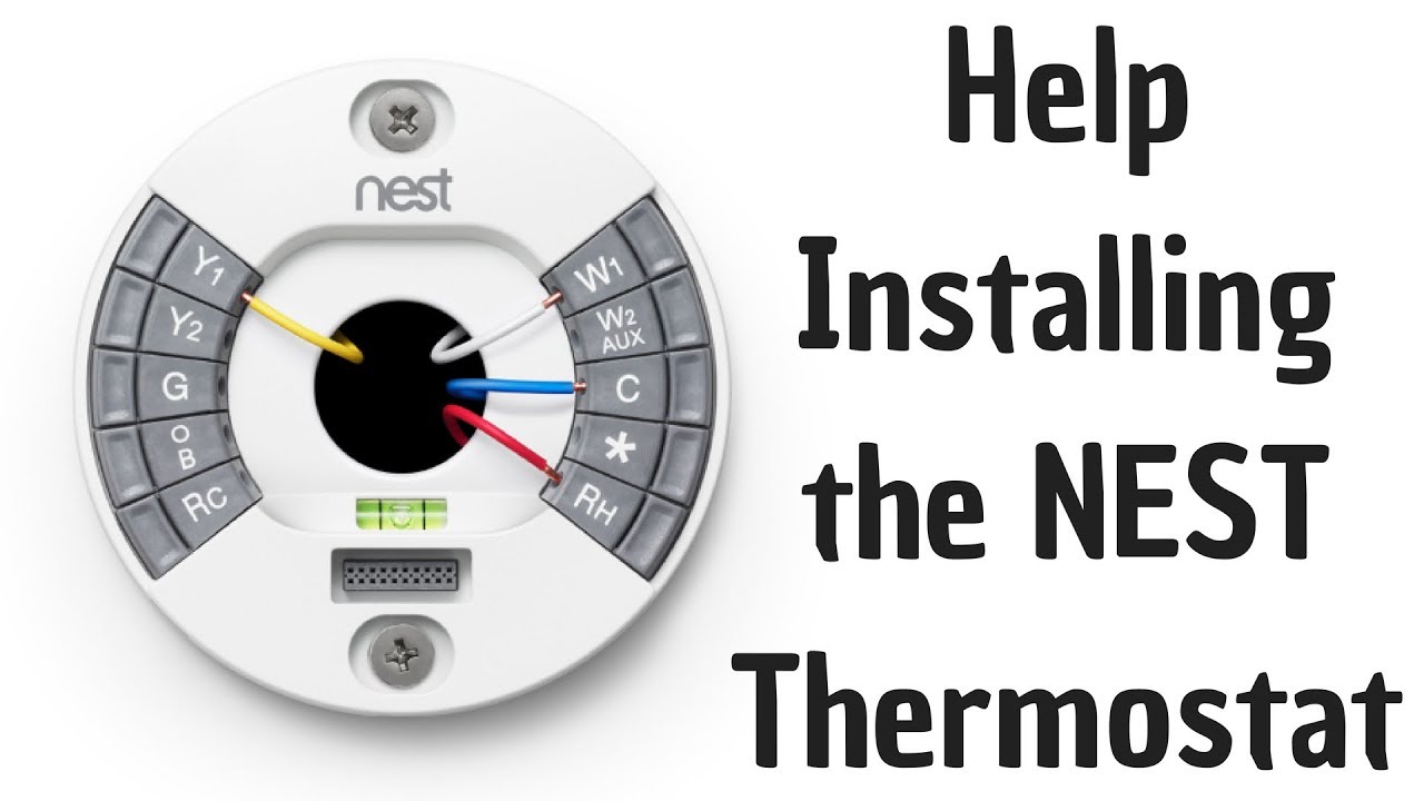
Help Installing The Nest Thermostat Youtube

Shop Diy Appliance Hvac Parts For All Your Air Conditioning And

White Rodgers 1e65 144 Electronic Non Programmable Line Voltage

Midea Air Conditioner Error Codes List And Definitions Error

Pin On Top 10 Best Wireless Thermostats Reviews
