Temco Control Transformer T01232 Wiring Diagram
Temco Control Transformer T01232 Wiring Diagram Wiring Diagram
Temco Control Transformer T01232 Wiring Diagram Wiring Database

Wrg 2570 International 4000 Series Wiring Diagram
Ssr Lazer 5 Schematics Wiring Diagram
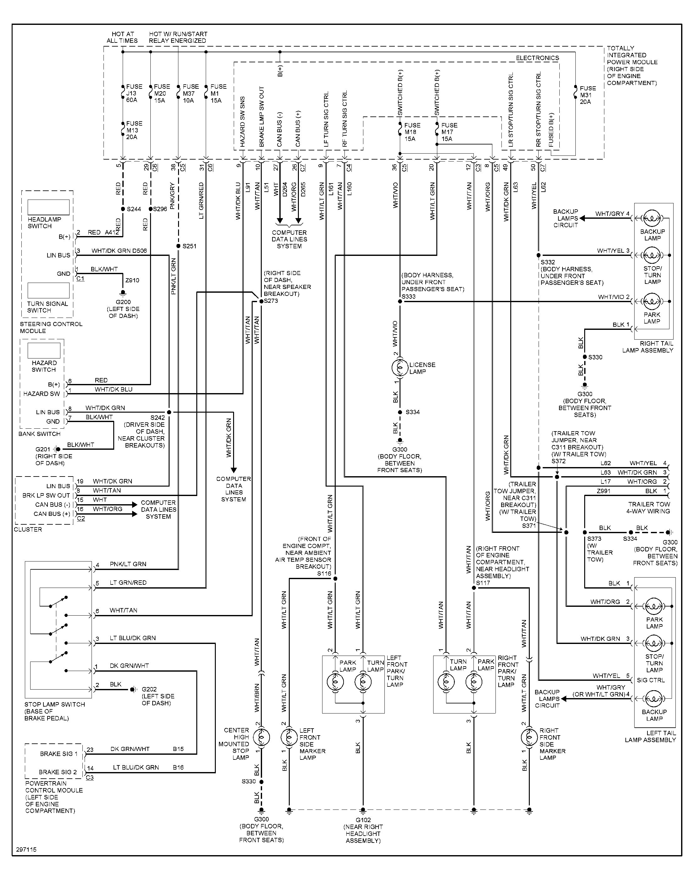
Liberty Tail Light Wiring Diagram Wiring Diagram
Cub Cadet 982 Kohler Wiring Diagram Wiring Diagram

To ensure compatibility check the wiring diagram by clicking a part number and viewing its product page.
Temco control transformer t01232 wiring diagram. It reveals the components of the circuit as simplified forms and also the power and signal links in between the gadgets. All of temco s medium voltage transformers are rated for 60 hz. Select a transformer that will operate on the supply voltage available at your facility example. A wiring diagram is a streamlined traditional photographic depiction of an electric circuit.
Temco single phase control transformer selection guide. Variety of control transformer wiring diagram. 607 north central avenue wood dale il 60191 1452 usa phone. Wiring is made easy by the solidly fixed terminals with standard combination slotted robertson head screw connections.
240x480 230x460 220x440 pri 120 115 110 sec 0 05 kva 50 60 hz 1 ph open copper encapsulated learn more. A wiring diagram is a simplified traditional photographic depiction of an electrical circuit. Is a manufacturer of low cost control systems and end devices for heating ventilating and air conditioning hvac applications. It shows the components of the circuit as streamlined forms and the power and signal connections in between the devices.
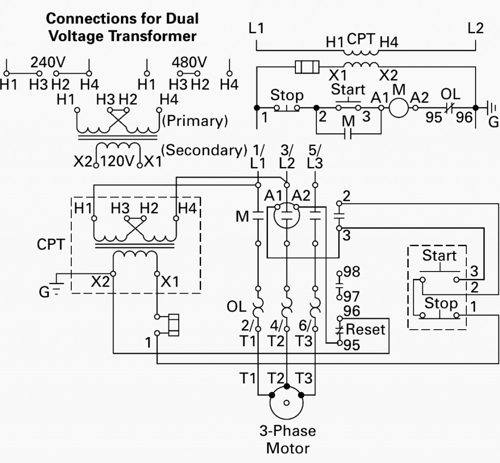
Temco s transformers are built to last guaranteed. 120v 240v or 480v. 480v primary three phase control transformers temco s three phase control transformers are copper wound and built with heat proof insulation for compact size and long life. Figure 4 control power transformer wiring diagram the leads from the primary of the transformer are connected to l1 and l2 on the starter.
Medium voltage transformer selection guide. Single phase control transformer selection guide. 2400v 4160v or 7200v. Temco industrial control transformers are used to convert all standard international voltages.
Check the connection diagram which temco includes on each product page to ensure compatibility. Many models are dual frequency rated for 50 and 60 hz.

Citroen 2cv Ignition Wiring Diagram Wiring Diagram

Bcf Amf Panel Wiring Diagram Pdf Wiring Resources

59e4ba Smart Fortwo Ecu Wiring Diagram Wiring Resources
2000 Plymouth Neon Fuse Box Location Wiring Diagram

480d 2005 Tahoe Radio Wiring Diagram Wiring Library

3b9333 Nissan Td27 Wiring Diagram Wiring Resources
Ffb1a5 Saab Cd Changer Wiring Diagram Wiring Resources
Zoeller Wiring Diagram Wiring Diagram

Cad5 Lexus Sc400 Engine Diagram Wiring Library
399817 Jeep Wrangler Front Light Wiring Diagram Wiring Library

Ad3d Hyundai Trajet Fuse Box Diagram Wiring Resources

09f7 99 Legacy Power Mirror Wiring Wiring Library

Temco Wire Relay Diagram 5 Kuiyt Balmoond15 Mooiravenstein Nl
